BSNL SET Telecom Notes
Free chapter for students preparing for BSNL SET.
Every phone call you make follows a fixed chain: your voice is captured as an electrical signal → converted to digital form → transmitted → reconstructed at the other end. Signal processing is the science behind each step of that chain. This page covers the concepts you are most likely to encounter in the BSNL SET exam.
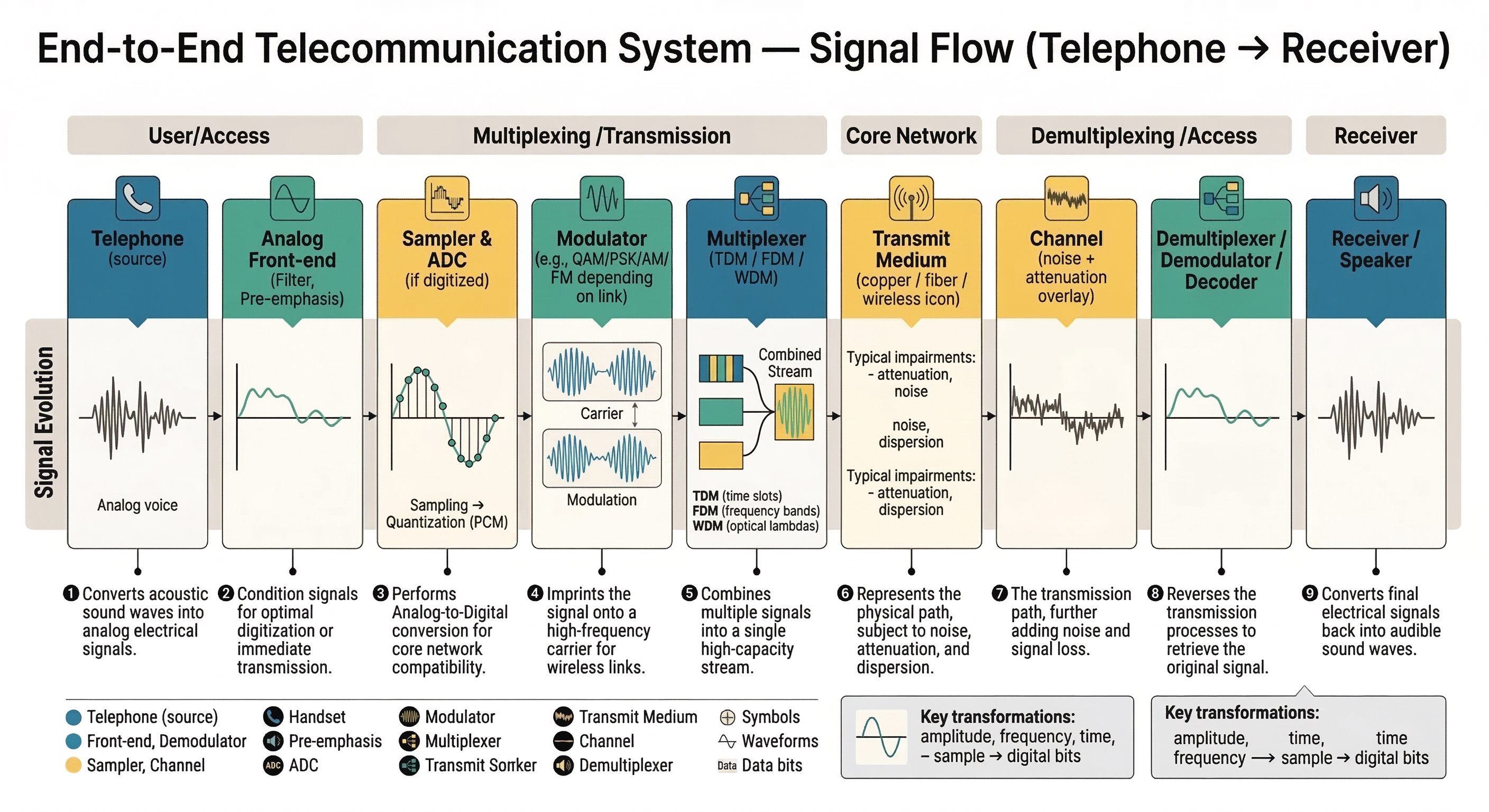 A complete telecommunication system: voice → electrical signal → sampled and digitized → transmitted → reconstructed at the receiver.
A signal is any quantity (voltage, current, light intensity) that varies with time to carry information.
| Type | What it means | Example |
|---|---|---|
| Analog (Continuous) | Varies smoothly at every instant | Human voice, temperature |
| Digital (Discrete) | Takes only specific values (0 or 1) | Data on a computer network |
| Periodic | Repeats after a fixed time interval (period T) | Sine wave, clock signal |
| Aperiodic | Does not repeat | A single voice burst |
| Deterministic | Fully predictable from a formula | Sine wave carrier |
| Random (Stochastic) | Cannot be predicted exactly | Thermal noise |
Key definitions:
Telecom fact: A telephone voice channel occupies 300 Hz to 3400 Hz, giving it a bandwidth of about 3.1 kHz.
The telecom world shifted from analog to digital because digital signals are far more resistant to noise and easier to process, store, and transmit.
| Property | Analog | Digital |
|---|---|---|
| Signal form | Continuous waveform | Discrete bits (0 and 1) |
| Noise impact | Accumulates along the route | Can be detected and corrected |
| Regeneration | Signal degrades with distance | Can be perfectly regenerated |
| Processing | Harder to manipulate | Easy to process with computers |
| Example systems | Old PSTN telephone, AM/FM radio | GSM, fiber optic, internet |
Exam point: Digital signals are preferred in modern telecom because noise does not accumulate — repeaters regenerate the exact bit pattern, not a degraded waveform.
To convert an analog signal to digital, we first sample it — we measure its value at regular time intervals.
Nyquist Sampling Theorem: To perfectly reconstruct a signal, the sampling frequency must be at least twice the highest frequency in the signal.
This minimum value () is called the Nyquist rate.
Standard telephony example:
If sampling is done at a rate lower than the Nyquist rate, high-frequency components appear as wrong lower frequencies in the digital signal. This distortion is called aliasing.
Prevention: An anti-aliasing filter (a low-pass filter) is placed before the sampler to remove all frequencies above before sampling. This is a mandatory step in any ADC (Analog-to-Digital Converter) design.
Exam point: Anti-aliasing filtering always happens before sampling, never after.
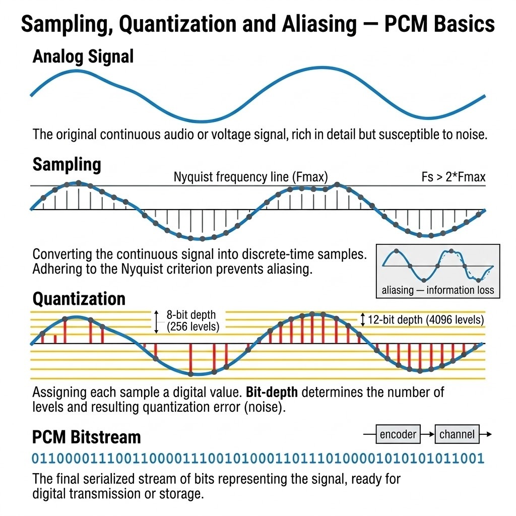 Sampling process, aliasing effect when sampling rate is too low, quantization levels, and the PCM encoding chain.
After sampling, each sample has a continuous amplitude value. Quantization rounds each sample to the nearest level from a fixed set of discrete levels.
| Bits (N) | Levels () | Typical use |
|---|---|---|
| 8 | 256 | Standard telephony (G.711) |
| 16 | 65,536 | CD-quality audio |
Quantization noise: The small error introduced by rounding is called quantization noise. More bits means smaller rounding error and better Signal-to-Noise Ratio (SNR).
Rule of thumb (exam-relevant): Each additional bit of quantization improves SNR by approximately 6 dB. An 8-bit PCM system gives roughly 50 dB SNR.
PCM is the standard method for converting an analog voice signal into a digital bitstream. It is the foundation of all digital telephony.
PCM process (in order):
Calculating the bitrate of a PCM voice channel:
This is why a standard digital voice channel is always 64 kbps. This is the building block of all E1/T1 multiplexed telephony systems.
Companding (G.711): To make better use of the 8 bits for quieter sounds, the quantization steps are made non-uniform — finer at low amplitudes and coarser at high amplitudes. Two international standards exist:
Exam point: India follows the A-law companding standard. The G.711 ITU standard defines 64 kbps PCM voice coding.
A filter is a circuit or algorithm that allows certain frequencies to pass while blocking others.
| Filter type | What it passes | Typical use |
|---|---|---|
| Low-Pass Filter (LPF) | Frequencies below a cut-off | Anti-aliasing, voice channel limiting |
| High-Pass Filter (HPF) | Frequencies above a cut-off | Removing DC components |
| Band-Pass Filter (BPF) | A specific range of frequencies | Selecting a radio channel |
| Band-Stop / Notch Filter | Blocks a specific range | Removing 50 Hz power-line interference |
Digital filters are broadly classified into two types based on how they process previous outputs:
| Property | FIR (Finite Impulse Response) | IIR (Infinite Impulse Response) |
|---|---|---|
| Feedback | No (feed-forward only) | Yes (uses past outputs) |
| Stability | Always stable | Can become unstable |
| Phase response | Linear phase (no distortion) | Non-linear phase |
| Efficiency | Needs more coefficients | More efficient (fewer coefficients) |
| Use case | When phase accuracy matters | When efficiency matters |
Exam point: FIR filters have no feedback and are always stable. IIR filters use feedback and can be unstable.
Every signal can be described either in the time domain (how it varies over time) or the frequency domain (which frequencies it contains and at what strength).
The Fourier Transform is the mathematical tool that converts a signal from time domain to frequency domain. You do not need to evaluate the transform formula for the exam — what matters is understanding what it tells you:
Power Spectral Density (PSD): Describes how the power of a signal is spread across frequencies. Wider bandwidth = more frequencies = more PSD spread.
Noise is any unwanted signal that interferes with the desired signal.
Signal-to-Noise Ratio (SNR) measures how strong the signal is compared to the noise:
Higher SNR = better quality. A value of 0 dB means signal and noise are equally strong; 40 dB means the signal is 10,000 times stronger than the noise.
Common noise types in telecom:
Exam point: Thermal noise (also called Johnson noise) is present in all conductors and cannot be eliminated — only minimized by design.
Modulation shifts a low-frequency baseband signal onto a higher-frequency carrier for transmission. This is done because low-frequency signals cannot travel long distances efficiently through air.
| Type | What changes on the carrier | Key use |
|---|---|---|
| AM (Amplitude Modulation) | Amplitude of the carrier | AM radio, DSB/SSB links |
| FM (Frequency Modulation) | Frequency of the carrier | FM radio, VHF communications |
| PM (Phase Modulation) | Phase of the carrier | Basis of digital modulations (PSK) |
Demodulation is the reverse — extracting the original baseband signal from the modulated carrier at the receiver.
Multiplexing lets multiple signals share a single transmission medium simultaneously.
| Type | How it divides the medium | Telecom use |
|---|---|---|
| FDM (Frequency Division Multiplexing) | Different frequency bands | Analog telephone trunk lines, cable TV |
| TDM (Time Division Multiplexing) | Different time slots | E1/T1 digital lines, SONET/SDH |
| WDM (Wavelength Division Multiplexing) | Different wavelengths (colors) of light | Fiber optic networks |
| CDM (Code Division Multiplexing) | Different spreading codes | CDMA mobile networks |
TDM and PCM together: An E1 line carries 32 TDM channels, each a 64 kbps PCM voice stream. Total bitrate = .
| Topic | Remember this |
|---|---|
| Nyquist / Sampling theorem | |
| Voice sampling rate in PSTN | 8,000 samples/sec (8 kHz) |
| PCM voice bitrate | 64 kbps (8000 × 8 bits) |
| Quantization levels for N bits | |
| SNR improvement per bit | ~6 dB per bit added |
| Companding standard in India | A-law (G.711) |
| Anti-aliasing filter is placed | Before the sampler |
| FIR filter characteristic | No feedback, always stable, linear phase |
| IIR filter characteristic | Has feedback, efficient, can be unstable |
| Aliasing cause | Sampling below Nyquist rate |
| E1 line bitrate | 2.048 Mbps (32 channels × 64 kbps) |
| Thermal noise | Present in all conductors; unavoidable |